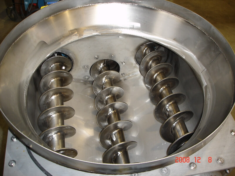
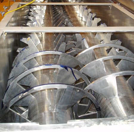
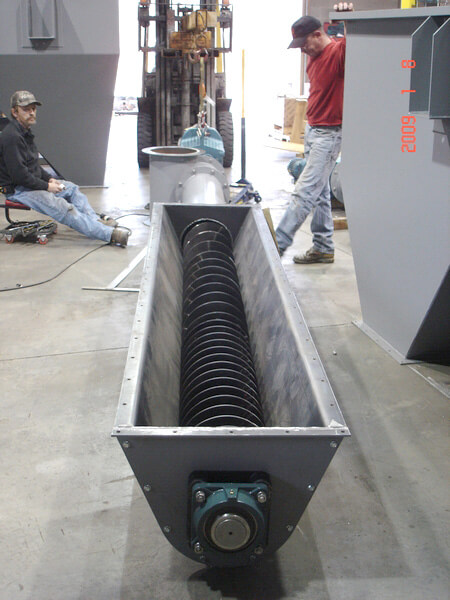
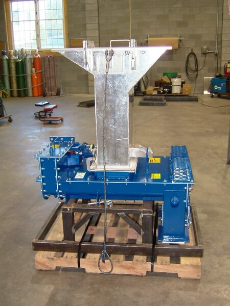
Screw Feeders
A screw feeder must be designed to receive material consistently and discharge it at a controlled rate. For accurate metering, the inlet must remain completely filled, and the screw flights beneath it must be engineered to regulate drawdown and loading. Proper shroud design, flight pitch, and inlet geometry ensure smooth material flow, prevent compaction and degradation, and reduce wear on the equipment.
Critical Design Factors for Efficient Screw Feeders
An effective screw feeder must have the inlet filled at all times. The design of the flight pitches under the inlet will control the product draw down in the inlet and subsequent product loading in the conveying portion of the housing after the inlet. There will always be a section of shroud after the inlet. This creates a round conveying path that the screw draws through. With this round conveying path the screw can only convey the material that has fallen into the flight pocket in the inlet. Material flow into the inlet of the screw feeder is also critical. The screw feeder can not meter material out of the inlet unless the material uniformly fills the flight pockets in the inlet.
On a screw feeder, product degradation, product compaction and equipment wear are all considerations. Particular care needs to be taken with the layout of the progressive pitch flights through the inlet and under the shroud as well as the length and shape of the displacement pipe sleeve or cone in the inlet section.

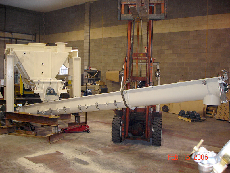
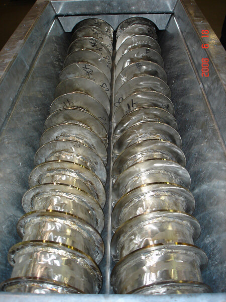
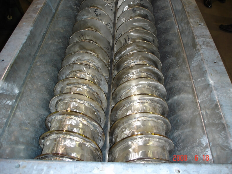
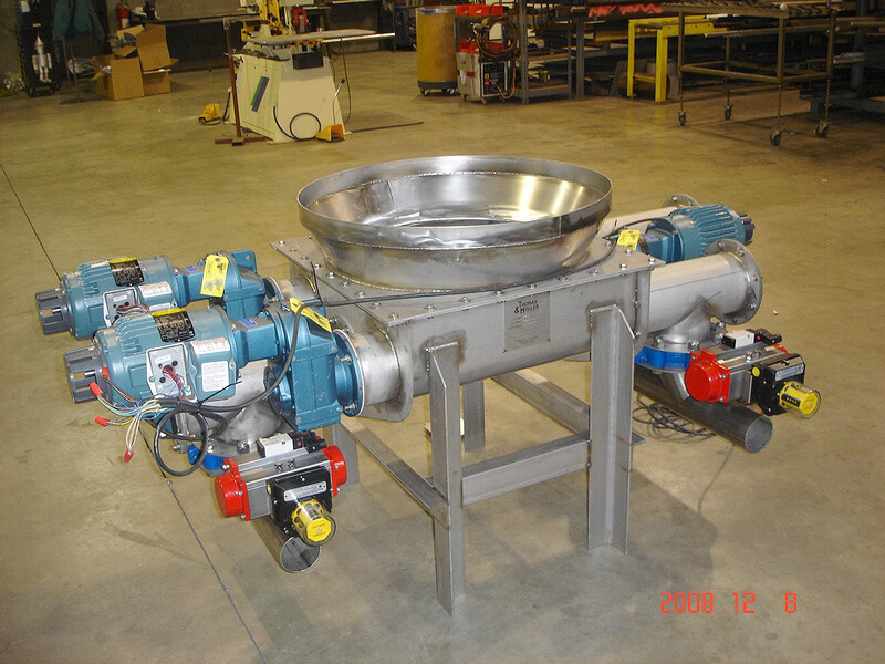
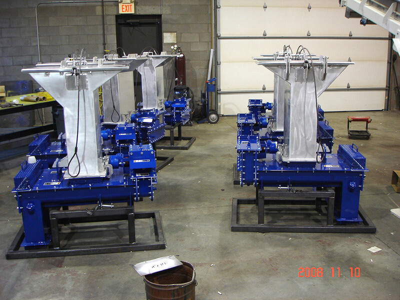
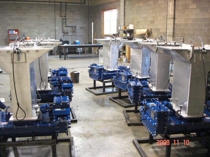
Screw Feeder Examples